Wednesday, 9 January 2013

6. Constraints

Polygon Count
The two common measurements of an object's 'cost’ or file size are the polygon count and vertex count. For example, a game character may stretch anywhere from 200-300 polygons, to 40,000+ polygons. A high-end third-person console or PC game may use many vertices or polygons per character, and an iOS tower defence game might use very few per character.

Polygons Vs. Triangles
When a game artist talks about the poly count of a model, they really mean the triangle count. Games almost always use triangles not polygons because most modern graphic hardware is built to accelerate the rendering of triangles.
Polygons however do have a useful purpose in game development. A model made of mostly four-sided polygons (quads) will work well with edge-loop selection & transform methods that speed up modelling, make it easier to judge the "flow" of a model, and make it easier to weight a skinned model to its bones. Artists usually preserve these polygons in their models as long as possible. When a model is exported to a game engine, the polygons are all converted into triangles automatically. However different tools will create different triangle layouts within those polygons. A quad can end up either as a "ridge" or as a "valley" depending on how it's triangulated.

 
Triangle Count vs. Vertex Count
Vertex count is ultimately more important for performance and memory than the triangle count, but for historical reasons artists more commonly use triangle count as a performance measurement. On the most basic level, the triangle count and the vertex count can be similar if the all the triangles are connected to one another. 1 triangle uses 3 vertices, 2 triangles use 4 vertices, 3 triangles use 5 vertices, and 4 triangles use 6 vertices and so on. However, seams in UVs, changes to shading/smoothing groups, and material changes from triangle to triangle etc. are all treated as a physical break in the model's surface, when the model is rendered by the game. The vertices must be duplicated at these breaks, so the model can be sent in renderable chunks to the graphics card.
Overuse of smoothing groups, over-splittage of UVs, too many material assignments (and too much misalignment of these three properties), all of these lead to a much larger vertex count. This can stress the transform stages for the model, slowing performance. It can also increase the memory cost for the mesh because there are more vertices to send and store.


Rendering
Rendering is the final process of creating the actual 2D image or animation from the prepared scene. This can be compared to taking a photo or filming the scene after the setup is finished in real life. Several different, and often specialised, rendering methods have been developed. These range from the distinctly non-realistic wireframe rendering through polygon-based rendering, to more advanced techniques such as: scanline rendering, ray tracing, or radiosity. Rendering may take from fractions of a second to days for a single image/frame. In general, different methods are better suited for either photo-realistic rendering, or real-time rendering.

Real-time
Rendering for interactive media, such as games and simulations, is calculated and displayed in real time, at rates of approximately 20 to 120 frames per second. In real-time rendering, the goal is to show as much information as possible as the eye can process in a fraction of a second, i.e. one frame. The primary goal is to achieve an as high as possible degree of photorealism at an acceptable minimum rendering speed (usually 24 frames per second, as that is the minimum the human eye needs to see to successfully create the illusion of movement). In fact, exploitations can be applied in the way the eye 'perceives' the world, and as a result the final image presented is not necessarily that of the real-world, but one close enough for the human eye to tolerate. Rendering software may simulate such visual effects as lens flares, depth of field or motion blur. These are attempts to simulate visual phenomena resulting from the optical characteristics of cameras and of the human eye. These effects can lend an element of realism to a scene, even if the effect is merely a simulated artefact of a camera. This is the basic method employed in games, interactive worlds and VRML.


Non Real-time
Animations for non-interactive media, such as feature films and video, are rendered much more slowly. Non-real time rendering enables the leveraging of limited processing power in order to obtain higher image quality. Rendering times for individual frames may vary from a few seconds to several days for complex scenes. Rendered frames are stored on a hard disk then can be transferred to other media such as motion picture film or optical disk. These frames are then displayed sequentially at high frame rates, typically 24, 25, or 30 frames per second, to achieve the illusion of movement.

When the goal is photo-realism, techniques such as ray tracing or radiosity are employed. This is the basic method employed in digital media and artistic works. Techniques have been developed for the purpose of simulating other naturally-occurring effects, such as the interaction of light with various forms of matter. Examples of such techniques include particle systems (which can simulate rain, smoke, or fire), volumetric sampling (to simulate fog, dust and other spatial atmospheric effects), caustics (to simulate light focusing by uneven light-refracting surfaces, such as the light ripples seen on the bottom of a swimming pool), and subsurface scattering (to simulate light reflecting inside the volumes of solid objects such as human skin).

The rendering process is computationally expensive, given the complex variety of physical processes being simulated. Computer processing power has increased rapidly over the years, allowing for a progressively higher degree of realistic rendering. Film studios that produce computer-generated animations typically make use of a render farm to generate images in a timely manner. However, falling hardware costs mean that it is entirely possible to create small amounts of 3D animation on a home computer system. The output of the renderer is often used as only one small part of a completed motion-picture scene. Many layers of material may be rendered separately and integrated into the final shot using compositing software.

Reflection/Scattering - How light interacts with the surface at a given point
Shading - How material properties vary across the surface

5. 3D Development Software

3DS MAX


Autodesk 3ds Max, formerly 3D Studio Max, is a 3d development suite for making 3D animations, models, and images. It has modeling capabilities, a flexible  It is frequently used by video game developers, TV commercial studios and architectural visualization studios. It is also used for movie effects and movie pre-visualization.

In addition to its modeling and animation tools, the latest version of 3ds Max also features shaders (such as ambient occlusion and subsurface scattering), dynamic simulation, particle systems, radiosity, normal map creation and rendering, global illumination, a customizable user interface, and its own scripting language.


http://en.wikipedia.org/wiki/Autodesk_3ds_Max


MAYA


Autodesk Maya, commonly shortened to Maya, is 3D computer graphics software that runs on Microsoft Windows, Mac OS and Linux, currently owned and developed by Autodesk, Inc. It is used to create interactive 3D applications, including video games, animated film, TV series, or visual effects. The product is named after the Sanskrit word Maya, the Hindu concept of illusion.


Maya 1.0 was released in February 1998. Following a series of acquisitions, Maya was bought by Autodesk in 2005. Under the name of the new parent company, Maya was renamed Autodesk Maya. However, the name "Maya" continues to be the dominant name used for the product.


Lightwave

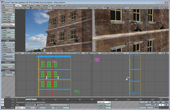
 LightWave is a software package used for rendering 3D images, both animated and static. It includes a rendering engine that supports such advanced features as realistic reflection and refraction, radiosity, and caustics. The 3D modeling component supports both polygon modeling and subdivision surfaces. The animation component has features such as reverse and forward kinematics for character animation, particle systems and dynamics. Programmers can expand LightWave's capabilities using an included SDK which offers LScript scripting (a proprietary scripting language) and common C language interfaces.


http://en.wikipedia.org/wiki/LightWave_3D


Blender

Blender is a free and open-source 3D computer graphics software product used for creating animated films, visual effects, interactive 3D applications or video games. Blender's features include 3D modeling, UV unwrapping, texturing, rigging and skinning, fluid and smoke simulation, particle simulation, animating, match moving, camera tracking, rendering, video editing and compositing. It also features a built-in game engine.


Cinema 4D

CINEMA 4D is a 3D modeling, animation and rendering application developed by MAXON Computer GmbH of Friedrichsdorf, Germany. It is capable of procedural and polygonal/subd modeling, animating, lighting, texturing, rendering, and common features found in 3d modelling applications.

http://en.wikipedia.org/wiki/Cinema_4D


ZBrush

ZBrush is a digital sculpting tool that combines 3D/2.5D modeling, texturing and painting. It uses a proprietary "pixol" technology which stores lighting, colour, material, and depth information for all objects on the screen. The main difference between ZBrush and more traditional modelling packages is that it is more akin to sculpting.

 
ZBrush is used as a digital sculpting tool to create high-resolution models (up to ten million polygons) for use in movies, games, and animations. It is used by companies ranging from ILM to Electronic Arts. ZBrush uses dynamic levels of resolution to allow sculptors to make global or local changes to their models. ZBrush is most known for being able to sculpt medium to high frequency details that were traditionally painted in bump maps. The resulting mesh details can then be exported as normal maps to be used on a low poly version of that same model. They can also be exported as a displacement map, although in that case the lower poly version generally requires more resolution. Or, once completed, the 3D model can be projected to the background, becoming a 2.5D image (upon which further effects can be applied). Work can then begin on another 3D model which can be used in the same scene. This feature lets users work with extremely complicated scenes without heavy processor overhead.


Personally, I have only used 3D studio Max, Light wave and Blender, I find 3Ds max easiest to use, and now that’s just me while others prefer to use blender and such others. Each of the software however has its given audience, Google’s ‘Sketch up’ is used by Architects, Maya is mainly used for 3D effects in TV and films, and 3DS max is used for modeling objects for games. Even though there are many of them, they all achieve the same result, which is to create 3D polygon objects. The only thing different between each software is the Use interface and some of the behind-the-scene stuff like how they render.


File Formats

 
Each 3D application allows the user to save their work, both objects and scenes, in a proprietary file format and export in open formats.
A proprietary format is a file format where the mode of presentation of its data is the intellectual property of an individual or organisation which asserts ownership over the format. In contrast, a free format is a format that is either not recognised as intellectual property, or has had all claimants to its intellectual property release claims of ownership. Proprietary formats can be either open if they are published, or closed, if they are considered trade secrets. In contrast, a free format is never closed.
Proprietary formats are typically controlled by a private person or organization for the benefit of its applications, protected with patents or as trade secrets, and intended to give the license holder exclusive control of the technology to the (current or future) exclusion of others.
Examples of proprietary formats, AutoCAD - .dxf, 3D Studio Max - .3ds, Maya - .mb, LightWave - .lwo
Examples of open formats,  .obj and .dae.

Tuesday, 8 January 2013

3. Geometric Theory

Geometric theory is the 3D software interpreting a 2d screen, using a Cartesian coordinates to represent geometry in 3D space. When using a 3D Cartesian coordinate system, which you can find in 3DS Max, is that it consists of 3 axis which is X, Y and Z.


 A polygon mesh is a collection of vertices, edges and faces that defines the shape of a polyhedral object. The faces usually consist of triangles, quadrilaterals or other simple polygons, but it may also me composed of more general concave polygons, or polygons with holes. Various operations can be performed on meshes; these include Boolean logic, smoothing, simplification and many others. Polygon meshes are made up of different elements, these include, vertices, edges, faces, polygons and surfaces.


The basic object used in mesh modeling is vertex, a point in three dimensional space. Two vertices connected by a straight line become an edge. Three vertices, connected to each other by three edges, define a triangle, which is the simplest polygon in Euclidean space. More complex polygons can be created out of multiple triangles, or as a single object with more than 3 vertices. Four sided polygons (generally referred to as quads) and triangles are the most common shapes used in polygonal modeling. A group of polygons, connected to each other by shared vertices, is generally referred to as an element. Each of the polygons making up an element is called a face.
A group of polygons which are connected by shared vertices is referred to a mesh.
In order for a mesh to appear attractive when rendered, it is desirable that it be non-self-intersecting, meaning that no edge passes through a polygon. Another way of looking at this is that the mesh cannot pierce itself. It is also desirable that the mesh not contain any errors such as doubled vertices, edges, or faces.

2. Displaying 3D polygons

API

API, an abbreviation of application program interface, is a set of routines, protocols, and tools for building software applications. A good API makes it easier to develop a program by providing all the building blocks. Most operating environments, such as MS-Windows, provide an API so that programmers can write applications consistent with the operating environment. Although APIs are designed for programmers, they are ultimately good for users because they guarantee that all programs using a common API will have similar interfaces.


Direct3D

An API for manipulating and displaying three-dimensional objects. Developed by Microsoft, Direct3D provides programmers with a way to develop 3-D programs that can utilize whatever graphics acceleration device is installed in the machine.

 
http://www.webopedia.com/TERM/D/Direct3D.html

OpenGL

A 3-D graphics language developed by Silicon Graphics. There are two main implementations: Microsoft OpenGL, developed by Microsoft and Cosmo OpenGL, developed by Silicon Graphics. Microsoft OpenGL is built into Windows NT and is designed to improve performance on hardware that supports the OpenGL standard. Cosmo OpenGL, on the other hand, is a software-only implementation specifically designed for machines that do not have a graphics accelerator.

Graphics Pipeline 

In 3D computer graphics, the terms graphics pipeline or rendering pipeline most commonly refer to the way in which the 3D mathematical information contained within the objects and scenes are converted into images and video. The graphics pipeline typically accepts some representation of a three-dimensional primitive as input and results in a 2D raster image as output. OpenGL and Direct3D are two notable 3d graphic standards, both describing very similar graphic pipelines.
Per-vertex lighting and shading

Geometry in the complete 3D scene is lit according to the defined locations of light sources, reflectance, and other surface properties. Some (mostly older) hardware implementations of the graphics pipeline compute lighting only at the vertices of the polygons being rendered. The lighting values between vertices are then interpolated during rasterization. Per-fragment or per-pixel lighting, as well as other effects, can be done on modern graphics hardware as a post-rasterization process by means of a shader program.

 
Clipping

Geometric primitives that now fall completely outside of the viewing frustum will not be visible and are discarded at this stage.

Projection Transformation

In the case of a Perspective projection, objects which are distant from the camera are made smaller. This is achieved by dividing the X and Y coordinates of each vertex of each primitive by its Z coordinate. In an orthographic projection, objects retain their original size regardless of distance from the camera.

Viewport Transformation

The post-clip vertices are transformed once again to be in window space. In practice, this transform is very simple: applying a scale and a bias. At this point, the vertices have coordinates which directly relate to pixels in a raster.

Scan Conversion or Rasterisation

Rasterisation is the process by which the 2D image space representation of the scene is converted into raster format and the correct resulting pixel values are determined. From now on, operations will be carried out on each single pixel. This stage is rather complex, involving multiple steps often referred as a group under the name of pixel pipeline.

Texturing, Fragment Shading

At this stage of the pipeline individual fragments (or pre-pixels) are assigned a color based on values interpolated from the vertices during rasterization, from a texture in memory, or from a shader program.

Display

The final colored pixels can then be displayed on a computer monitor or other display.

http://en.wikipedia.org/wiki/Graphics_pipeline

1. Applications of 3D


3D in Games
In games 3D is needed to create detailed world, items and characters, 3D can offer games a spectacular amount of realism for games see the video below for more:

Games started to transition to 3d, when games like Star Fox, and virtual racer used 3D to move around in environments. However, 3D really hit it off on the Nintendo 64, with games like crash bandicoot. The ability to move away from the classic side scrolling such games, allowed for more complex and interactive games and genres. Due to games transitioning the use of cartridges went down as developer’s use CD’s due to the more storage capacity.

Most games now are developed in 3d, with each generation of games making more complex systems to use. Creating realistic environments and characters for the players to get attached to the game, a metaphor for games being live-action novels would be appropriate. With more and more detailed 3d animations the characters and environment become more and more realistic.


3D in Animation
Modern animation encompasses 3D computer graphics, essentially being the successor to stop motion techniques used in tradition animation. Computer generated animations are much easier to control than other physical forms. It will also allow the production of actors, expensive set pieces or props, without the financial setback.

Some of the earliest work of 3D animation was in the first half of the 1960’s by Edward zajac, Frank Sinden, Kenneth Knowlton and Michael Noll. The first feature-length computer animation film was in 1995 with the film, Toy Story by Pixar.

 
The availability and affordability of high-end 3d software has allowed individuals to use the technology and create animations that are of professional quality. 3D animation is created by key-framing he camera, lights and objects within the scene, more organic forms are controlled by rigging and motion capture technics to create realistic movement. Rigging is basically giving the body or ‘mesh’ of a model, bones or a skeleton which is used to move and pose the model. This technique is often used to animate organic life, such as humans and animals, however this can also be applied to any object, such as a fork or wires.
An example of rigging a hand:
Motion capture is another technique; it is the recording of motion of humans or animals. In film making and video game development, it refers to recording actions of human actors, and using that information to animate digital character models in 3D computer animation. A performer wears marks near each joint to identify the motion by the positions or angles between the markers. Acoustic, unertial, LED, magnetic or reflective markers or combinations of any of these, are tracked, optimally at least two times the frequency rate of the desired motion.
3D in Film and TV
The first revolutionary use of 3D in a movie was in Jurassic Park in 1993, almost all the dinosaurs were vreated using 3D CGI and shown in the live action scene of the movie;


It is now common for films to have 3D aspects in them; full-length 3d animation films are also in commonplace.
Compositing:
Compositing is the combining of visual elements from separate sources into single images, often to create the illusion that all the elements are parts of the same scene. Today, most, not all, compositing is achieved through digital image manipulation, in the digital method of compositing, software commands designate a narrowly defined colour as the part of an image to be replaced. Then every pixel from another image, aligned to appear as part of the original. For example, a TV weather person is recorded in front of a plain blue or green screen, which compositing software replaces only the designated blue or green colour with weather maps.

3D hardly appeared on television until 1994, when a Canadian production company called Mainframe Entertainment, released a CGI TV series called ReBoot. The series was credited to be the first ever full-length, completely computer animated TV series. As the cost of production has gone up, production values have started to mirror those of the film industry.

3D in Education
3D technology is used effectively to create educational tools and content. The software allows creating environments to use as diagrams while in the classroom, as well as bringing in objects to study, or you are able to walk through 3D environments, all of this to help educate students in the classroom. The full environments, such as the Roman City and Pond Ecosystem, allow teachers and pupils to explore and discover in a virtual environment. Using the camera function in the Viewer, teachers may individually determine and control the path they wish to travel inside any selected 3D environment. For instance, take the classroom on a virtual tour of ancient Giza or on an underwater hunt for tadpoles.

3D in Architecture
Architectures are able to create 3D building and enviroments. Also be able to produce finished visualisations of the finished deisgns.


3D in Engineering
Engineers use 3D technology to plan out their designs and test them.


3D in Medicine
3D technology in medicine is used to create 3d models in scans to moniore the human body, and it also mainly used for training purposes.


3D in Meteorology
3D technology is used to model weather systems to help understand upcoming patterns, particulary in the case of extreme weather conditions.


3D in Product Design
3d technology is used by designers to develop and visualise new products.

Wednesday, 30 May 2012

HA6 Task 5

Evaluation

HA6 Task 1
I did read the brief thoroughly and took an estimated guess of the timescale as to what point I would finish the assignment and concluded I might have not enough time to meet the deadline. Other than that I was perfectly clear on what I had to do and further questioning was not needed. I understood the way in which the assignment was designing and how the grades were awarded. I researched the product and client briefly before starting the assignment, I reflected heavily on the skills I developed during the introduction to modeller sessions, yet equally finding new and efficient ways to work in with the tools I was given. I did create a design pack for reference and kept refering back it later on in the production.

HA6 Task 2
Unfortunately I did not create a production log early on; however I did save the projects at a certain points in the production so I could later log them. This was done to achieve the most of the time I had allocated to creating the project. The log of diagrams I made, were clear and precise.

HA6 Task 3
I learned during the 3D modelling, that it’s good to experiment with different tools to try to get the right shape rather than sticking to the same few tools, I learnt that reference images are really important to get the the size and shape right for my character, I also learned that there are many different way to get the right shape while modelling.

HA6 Task 4
I believe my finished product achieved the aim of the project. As explained in [HA4 Task 1 – Outline] I understood the brief and what I needed to do, the assignment was clear to me, I reflected on the skills I had gained from the introduction to modeller sessions, along with my own knowledge. I planned out what needed to be done and when. However a weakness in my design process was probably delaying the time on making a production log when I should have done it while working on the project to be more time efficient, as explained in [Ha4 Task 2 – Plan]. Overall I am happy which my project I could have been more efficient but I was able to get the work done in an acceptable timeframe.

HA6 Task 4